.

INCLUDES RFID interfacing with avr GPS interfacing with avr RF Module interfacing with avr Stepper Motor With AVR
Showing posts with label Avr basic. Show all posts

Tuesday, December 20, 2011

Embedded Hardware and Software

HARDWARE

There are 3 stages in bringing out a hardware. They are:
  • Gathering idea about the circuit
  • Designing a circuit
  • Fabrication

Gathering idea about the circuit:

Making a hardware is very easy if we have some ideas about the components. For most of the electronic components like resistor, capacitor IC’s, etc., we have their working mode and data sheets on the internet itself. From that, we can gather ideas about the components. After it, integrating the components to one another will give the exact circuit which we desire.

Designing a circuit:

When we mix Yellow and Blue colour, we get green colour. This is a formula. Similarly, if we onnect a resistor and a transformer in series to a diode, we get a rectifier. By the same method, we can design the circuits by gathering a good integrating knowledge.

After designing the circuit, the circuit should be clearly drawn some where else. For drawing the circuit easily, we can use the software’s such as CIRCUIT MAKER, PROTEL, DESIGNWORKS etc, which may be downloaded from the internet. These software’s are user friendly, as they have pre-designed component library within them. From this library, we can take those components, and connect it easily through connectors. Then by Auto- Routing, we can deign the PCB layout also.

But, Auto-Routing method of framing the PCB layout is advisable only for large circuits and not for small circuits. For small circuits, it is better to design the PCB manually. For manual designing of PCB layout, we can use the software’s such as ORCAD, RIMUPCB, ExpressPCB., etc

Fabrication:

Now, the PCB layout is ready in our PC. We can take a print or draw this layout in the board. After copying the layout, the holes are drilled and the components are soldered. Now, the hardware is ready.

SOFTWARE

The software may be written either in BASIC, Assembly, C or C++. Beginners may practice with BASIC or Assembly. The software’s are written in packages like KEIL, RAID etc. These software’s gives a good cope-up for beginners.
[Note: Want to get sample embedded programs? Visit www.8051projects.info, www.8085projcts.info]

Why do we want to write them in Software packages? Is it not enough to write them in PC and load it in the microcontroller? Can you guess the reason?   The reason is - to load the program in the microcontroller, we need HEX data. Microcontroller can accept only hex inputs and not other inputs. Only for this purpose, we go for software packages or IDE (Integrated Development Environment). These packages are available with programmer, simulator and compiler togather. So, it is also called as IDE. These packages convert our program to hex code.

We can check our outputs immediately for each line in the program - using the simulator. The errors are easily noticed by the built-in compiler and are easily debugged. By this, we can get the exact program and the corresponding HEX codes. Now, how is it loaded in the microcontroller?

For loading the converted codes, we need a programming kit called programmer. The programmer kit can be bought from online shops or it can be designed with the help of some websites.

[Note: The circuit diagram for Programming kit is freely downloadable from www.avrprojects.info . This programming kit can be used to program all - AVR, and 8051 microcontrollers.]

These efforts may bring out good embedded products, and wish you all great success in your work. If you want more details regarding this, post it in the above said website.

Saturday, December 17, 2011

How to configure Watchdog Timers of AVR Microcontroller (ATmega16)

       Some high end applications require multiple or critical calculations to be done by the microcontroller. This may lead to cases when the controller enters into wrong or infinite loops. As a result of this, the system either hangs up or gets crashed. The solution to overcome these situations is to automatically reset the system whenever such a situation arises.

The Watchdog Timer is a hardware or software generated timer interrupt which reboots/resets the system in the situations mentioned above. The watchdog timers are also used in cases when you intentionally require resetting the system without any physical interference.
The AVR microcontroller has an in-built watchdog timer. This article explains the working of watchdog timer in ATmega16.

The Watchdog Timer is a special timer which can be enabled in any section of the code and when enabled it ensures that a certain number of instructions execute within a pre-defined time frame. This time frame or the time delay can be configured/set using the registers of the watchdog timer. In case the instructions execute within the time frame, watchdog timer needs to be turned off and the program execution continues. However, if the instructions fail to execute within this time frame (this conditions is called time out condition) the entire system reboots thus avoiding any system crash or hang up.

Watchdog Timer in ATmega16:
The Watchdog timer of Atmega16 can be configured by using WDTCR register of AVR microcontroller. When the time out condition is set, the watchdog timer starts counting clock cycles. The watchdog’s timer is clocked from separate on-chip watchdog oscillator of 1MHz frequency. The time out condition is set by configuring prescaler bits of WDTCR register.

WDTCR (Watch Dog Timer Control Register): 
  -          -         -         WDTOE      WDE       WDP2         WDP1       WDP0
Bit 7    Bit 6    Bit 5        Bit 4          Bit 3          Bit 2           Bit 1          Bit 0

  
WDTOE (Watch Dog Turn-Off Enable) – The watchdog timer is disabled by configuring WDTOE and WDE bits (explained later in the article).

WDE (Watch Dog Enable) – Watchdog timer is enabled by writing 1 to WDE bit.

WDP [2:0] (Watch Dog Prescaler) bits - These three bits determine the watchdog time out condition.
  
How Watchdog Timer works:
The watchdog timer starts when the WDE bit is enabled and prescaler bits are configured for time-out condition. As watchdog timer reaches time-out condition, watchdog timer is reset and generates a pulse of one clock cycle which resets the program counter. When watch dog timer resets the timer, the WDRF (Watch Dog Reset Flag) bit in MCUCSR register is set by the hardware. To disable the watchdog timer following steps must be followed:
1. Set the WDE and WDTOE bits in same clock cycle WDTCR register. The logic one must be written to WDE bit even though it is set to one already.
2. After four clock pulses, write logic 0 to the WDE bit. Otherwise watchdog timer will not be disabled.

Objective:
To set watchdog timer condition at 2 seconds (approx.) and check the reset condition.

Circuit diagram:
The connection for above mentioned objective is shown in circuit diagram. An LED is connected at pin PB0 which blinks continuously. Another LED is connected to PB1 pin. This LED will glow when watchdog time out condition occurs.

Programming steps:
1. Check the status of WDRF bit. If this bit is high, set the PB1 pin of the controller.
2. Set the WDE bit in WDTCR register to activate the watchdog timer.
3. Set the prescaler bits WDP [2:0] = 111 for the time-out condition of 2 sec.
4. Write an infinite loop to toggle the PB0 bits toggles with a certain delay.
5. On time-out condition, watchdog timer resets the controller and this event reinitialize the program counter to go back at step 1.


// Program to configure watchdog timer in ATmega16 Microcontroller
#include<avr/io.h>
#include<util/delay.h>

int main()
{
    DDRB=0x03;

    if(bit_is_set(MCUCSR,WDRF))
    {
        PORTB|=(1<<PB1);
        _delay_ms(1000);   
    }
   
    PORTB&=~(1<<PB1);
    WDTCR=0x0F;
    while(1)
    {
        PORTB|=(1<<PB0);
        _delay_ms(400);
        PORTB&=~(1<<PB0);
        _delay_ms(400);
    }
}

How to use inbuilt ADC of AVR microcontroller (ATmega16)

Microcontroller understands only digital language. However, the inputs available from the environment to the microcontroller are mostly analog in nature, i.e., they vary continuously with time. In order to understand the inputs by the digital processor, a device called Analog to Digital Converter (ADC) is used. As the name suggests this peripheral gathers the analog information supplied from the environment and converts it to the controller understandable digital format, microcontroller then processes the information and provides the desired result at the output end.

ATmega16 has an inbuilt 10 bit, 8-channel ADC system. Some of the basic features of Armega16 ADC are:
·         8 Channels.
·         10-bit Resolution.
·         Input voltage range of 0 to Vcc.
·         Selectable 2.56V of internal Reference voltage source.
·      AREF pin for External Reference voltage.
·      ADC Conversion Complete Interrupt.

ADC channels in Atmega16 are multiplexed with PORTA and use the common pins (pin33 to pin40) with PORTA. ADC system  of Atmega16 microcontroller consists of following pins:
        i.            ADC0-ADC7: 8 Channels from Pin 40 to Pin 33 of Atmega16 ADC peripheral.
      ii.            AREF: Pin32 of Atmega16 microcontroller, the voltage on AREF pin acts as the reference voltage for ADC conversion, reference voltage is always less than or equal to the supply voltage, i.e., Vcc.
      iii.            AVCC: Pin30, this pin is the supply voltage pin for using PORTA and the ADC; AVCC pin must be connected to Vcc (microcontroller supply voltage) to use PORTA and ADC.

Note:  External reference voltage source can be used at AREF pin. However, Atmega16 also has internal reference voltage options of 2.56V and Vref = Vcc.

Learn More About ADC REGISTERS form datasheet of ATMEGA16 available at downloads.


Circuit description
Connect the circuit as shown in the circuit diagram. A ceramic capacitor 104 is connected in between AVcc (pin 30) and Aref (pin 32). AVcc (pin 30) is connected to external supply +5V.

Code explanation
To interface analog device with AVR microcontroller, follow the following steps for programming it.


Step1: To initialize ADC
        i.            Set the value in ADMUX register according to the ADC channel and the reference voltage.
       ii.            Set the Prescaler bits accordingly in ADCSRA register.
      iii.            Set the ADEN bit to enable the ADC.
void ADC_init(void)        // Initialization of ADC
{
    ADMUX=(1<<REFS0);    // AVcc with external capacitor at AREF
    ADCSRA=(1<<ADEN)|(1<<ADPS2)|(1<<ADPS1)|(1<<ADPS0);   
                        // Enable ADC and set Prescaler division factor as 128
}

Step2: To read the analog value
        i.            Put the channel value in ADMUX
       ii.            Start the conversion by setting the ADSC bit.
      iii.            Monitor the ADIF bit for conversion complete.
      iv.            Clear the conversion bit ADIF. By writing it 1.
       v.            Digital converted result is now available in ADCH and ADCL registers.
unsigned int ADC_read(unsigned char ch)
{
    ch= ch & 0b00000111;        // channel must be b/w 0 to 7
    ADMUX |= ch;                // selecting channel

    ADCSRA|=(1<<ADSC);            // start conversion
    while(!(ADCSRA & (1<<ADIF)));    // waiting for ADIF, conversion complete
    ADCSRA|=(1<<ADIF);            // clearing of ADIF, it is done by writing 1 to it

    return (ADC);
}


//Program for ADC to read from channel 0 and show the 8 bit o/p on PORTB

#include<avr/io.h>
#include<util/delay.h>

void ADC_init(void);
unsigned int ADC_read(unsigned char);

// ------------------------------------------------
int main(void)
{
    unsigned int value;
    DDRB=0xFF;
    DDRD=0x03;
    ADC_init();    // Initialization of ADC
    // ch=0;
    while(1)
    {
        value=ADC_read(0);
        PORTB=value;
        _delay_ms(500);
    }
}
//------------------------------------------------

void ADC_init(void)        // Initialization of ADC
{
    ADMUX=(1<<REFS0);    // AVcc with external capacitor at AREF
    ADCSRA=(1<<ADEN)|(1<<ADPS2)|(1<<ADPS1)|(1<<ADPS0);   
                        // Enable ADC and set Prescaler division factor as 128
}

unsigned int ADC_read(unsigned char ch)
{
    ch= ch & 0b00000111;        // channel must be b/w 0 to 7
    ADMUX |= ch;                // selecting channel

    ADCSRA|=(1<<ADSC);            // start conversion
    while(!(ADCSRA & (1<<ADIF)));    // waiting for ADIF, conversion complete
    ADCSRA|=(1<<ADIF);            // clearing of ADIF, it is done by writing 1 to it

    return (ADC);
}

How to display text on 16x2 LCD using AVR microcontroller (ATmega16)

      This article is in continuation to the article Single character LCD display using AVR. The aforesaid article shows how to display a single letter on LCD. Moving forward towards learning to work with LCD, this article explains how to display a string on LCD. Displaying string is occasionally used in many applications.

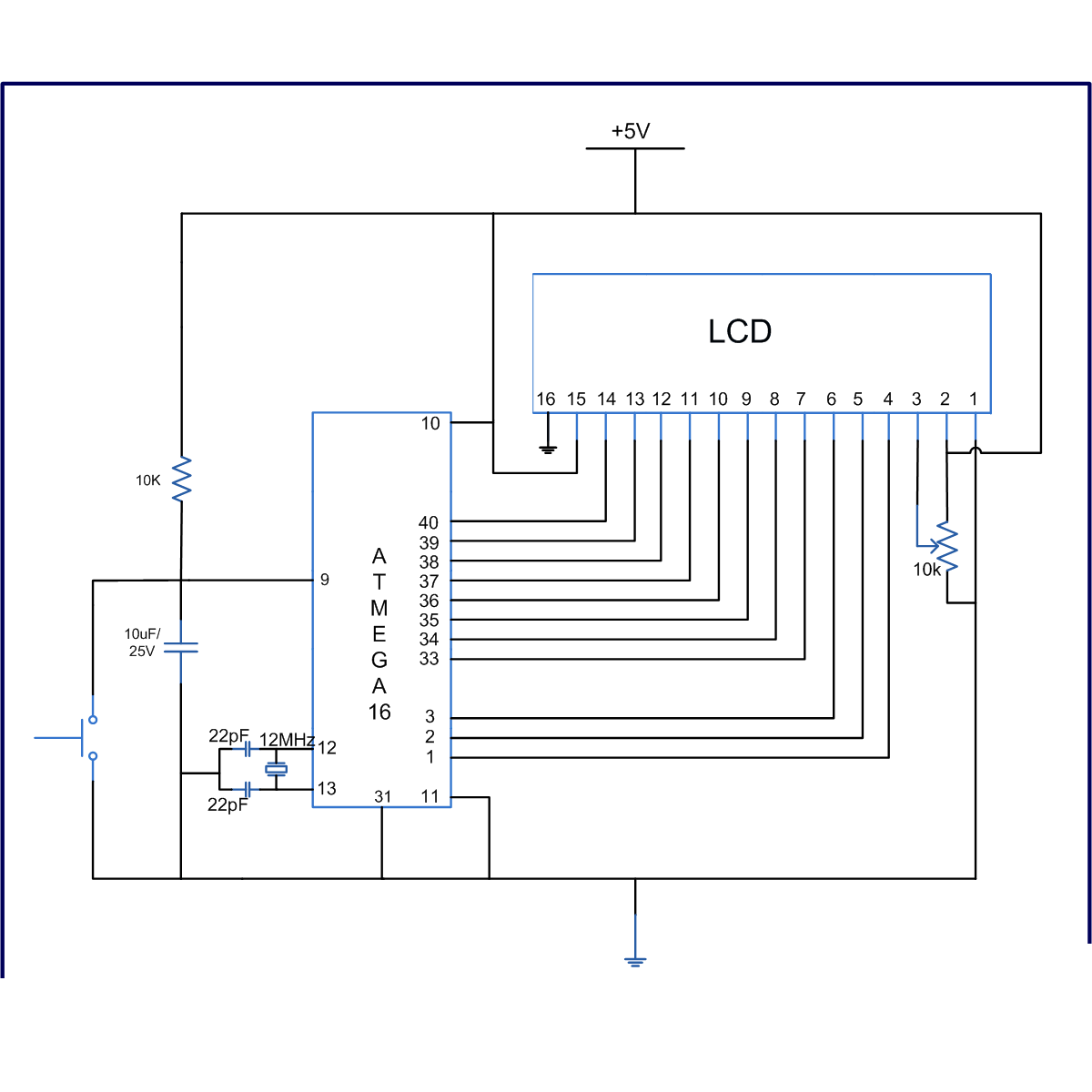
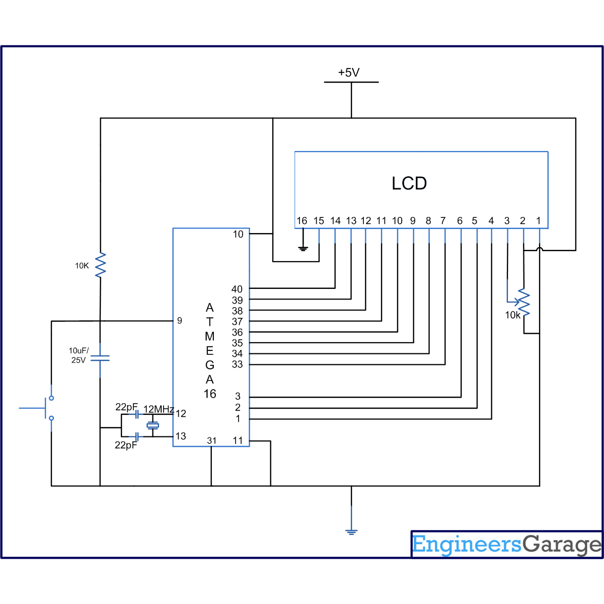
The connection of the LCD with the AVR microcontroller (ATmega16) is shown in the circuit diagram.
 

#define F_CPU 8000000

#include <avr/io.h>

#include <util/delay.h>

#define dataport PORTA

#define commport PORTD

#define rs PD4

#define wr PD5

#define en PD6

int LCD_init(void);

int LCD_SendData(void);

int wrcomm(void);

int wrdata(void);

int main(void)

{

DDRA = 0xFF; //Setting PortA as output port

DDRD = 0x70; //Setting PortD 4, 5, 6 pin as output pins

LCD_init(); //Initialise LCD

LCD_SendData( ); //Write to LCD

return 1;

}

int LCD_init()

{

dataport = 0x38; //initialize LCD 2 lines, 5x7 matrix

wrcomm(); //Right the command byte to command register

dataport = 0x01; //Clear LCD

wrcomm(); //Right the command byte to command register

dataport = 0x0E; //Display on Cursor Blinking

wrcomm(); //Right the command byte to command register

dataport = 0x80; //Cursor at line 1, position 1

wrcomm(); //Right the command byte to command register

dataport = 0x1C; //Shift Entire Display To Right

wrcomm(); //Right the command byte to command register

return 1;

}

/*********** **** <<Sending Data To LCD Display>> ************ ***/

int LCD_SendData(void)

{

unsigned char j[] = " PROELX TEST";

int i;

for(i = 0; i < sizeof j; i++)

{

dataport = j[i];

wrdata();

}

return 1;

}

/******* <<Righting the command byte to command register>> ********/

int wrcomm(void)

{

commport &= ~(1 << rs); //Setting RS = 0, selecting command register

commport &= ~(1 << wr); //Setting RW = 0

commport |= (1 << en); //EN = 1

commport &= ~(1 << en); //EN = 0, thus giving high to low pulse on Enable pin

_delay_ms(10); //10ms delay

return 1;

}

/********** <<Righting the Data byte to Data register>> **********/

int wrdata(void)

{

commport |= (1 << rs); //Setting RS = 1, selecting data register

commport &= ~(1 << wr); //Setting RW = 0

commport |= (1 << en); //EN = 1

commport &= ~(1 << en); //EN = 0, thus giving high to low pulse on Enable pin

_delay_ms(10) ; //10ms delay

return 1;

}

How to take input from a particular pin of ATmega16

       For understanding the human needs a system must be able to take input from user. The devices which can be used to take input for a system are keypad, touch screen, etc. In the article LED blinking, the microcontroller drives the LED or in embedded language the microcontroller was set to give o/p, this article gives brief information of getting an input from user at a particular pin of microcontroller.

In order to take input from an external source on any of the pins of the AVR microcontroller, the pins need to be configured as input pin. This configuration informs the controller that the corresponding pins are used to take input. The following steps explain how to take input from a pin:


Step1: Set the direction of PORT
To use a port as an input port first set the direction of port. DDRx (Data Direction) Register is used to set the direction of port.
DDRA=0x00;
In DDRA, ‘A’ shows the portA and 0x00 sets all the pins of port as input pins. (Writing 0 in DDR makes it input pin and writing 1 in DDR makes it output pin.

Step2: To take input form a port
Make a variable and use PINx instruction to get the input from a port
Value=PINA;
Where Value is a variable.

How to compare a pin?
To compare a pin, the instructions bit_is_set or bit_is_clear can be used. These instructions are define in avr/sfr_defs.h library. There is no need to include this library in code if avr/io.h has been included.

// Program to take input from a particular pin in AVR Microcontroller (ATmega16)
#include<avr/io.h>
#include<util/delay.h>

int main (void)
{
    unsigned int i=0;
    DDRA=~_BV(PA0);    // PA0 as input pin
    PORTA=0x00;
    DDRD=0xff;

while(1)
    {
        PORTD=0x01;
        while(PORTD!=0)
        {
            if(bit_is_set(PINA,PA0))        //If PA0=1
            {
                _delay_ms(100);

if(bit_is_set(PINA,PA0))    //Check it again due to swithc debouncing
                PORTD=(PORTD<<1);        //Left shift value of PORTD by 1
           
            }
           
        }
    }
}

USB Programmer for AVR


       USBasp - USB programmer for Atmel AVR controller's.USBasp is a USB in-circuit programmer for Atmel AVR controllers.It simply consists of an ATMega48 or an ATMega8 and a couple of passive components.The programmer uses a firmware-only USB driver, no special USB controller is needed.
Its Features are:-
Works under multiple platforms. Linux, Mac OS X and Windows are tested, No special controllers or smd components are needed, Programming speed is up to 5kBytes/sec, SCK option to support targets with low clock speed (< 1,5MHz, serial interface to target (e.g. for debugging)


In the Schematic note the following points:-
BLACK Wire is Ground .
RED Wire is Vcc 5V .
BROWN Wire is Data -.
GREEN Wire is Data +. 


Download
Firmware and circuit are available at http://www.fischl.de/usbasp/

Please refer to Readme.txt for details on building, installing and using USBasp.

Software used

1) AVRDUDE supports USBasp since version 5.2! Get AVRDUDE.
2)Khazama AVR Programmer is a Windows XP/Vista GUI application for USBasp and   avrdude.
3) eXtreme Burner - AVR is a Windows GUI Software for USBasp based USB AVR programmers.
All these Three softwares Are available at downloads...