.

INCLUDES RFID interfacing with avr GPS interfacing with avr RF Module interfacing with avr Stepper Motor With AVR
Showing posts with label interface. Show all posts

Tuesday, December 20, 2011

Reading and writing SD card using Atmega16

SD card

sdcard

Pin description of an SD card

Pin Name Function (SD Mode) Function (SPI Mode)
1 DAT3/CS Data Line 3 Chip Select/Slave (SS)
2 CMD/DI Command Line Mater Out Slave In (MOSI)
3 VSS1 Ground Ground
4 VDD Supply Voltage Supply Voltage
5 CLK Clock Clock (SCK)
6 VSS2 Ground Ground
7 DAT0/DO Data Line 0 Master In Slave Out (MISO)
8 DAT1/IRQ Data Line 1 Unused or IRQ
9 DAT2/NC Data Line 2 Unused

Important SD card commands

Command Argument Type Response Description
CMD0 None R1 Tell the card to reset and enter its idle state.
CMD16 32-bit Block Length R1 Select the block length.
CMD17 32-bit Block Address R1 Read a single block.
CMD24 32-bit Block Address R1 Write a single block.
CMD55 None
R1
Next command will be application-specific (ACMDXX).
CMD58 None R3 Read OCR (Operating Conditions Register).
ACMD41 None R1 Initialize the card.

Initialize SD card

Initialization begins by setting the SPI control clock signal to 400kHz, which is required for compatibility of most SD and MCC memory cards. Then reset the tab order at CMD0 activated CS input card (CS at level L). CRC byte for the command CMD0 and zero argument command is 0x95. CMD55 followed orders and ACMD41. If after the idle bit in the level L handshake is completed and anticipates that further management framework. Command CMD58 For example, we check whether the card supports the same supply voltage as the MCU, which is typically in the range of 2.7 V to 3.6 V. SPI clock signal to set the maximum allowed value.

Program part

SD card connection to microcontroller
#define DI 6                         // Port B bit 6 (pin7): data in (data from MMC)
#define DT 5                        // Port B bit 5 (pin6): data out (data to MMC)
#define CLK 7                     // Port B bit 7 (pin8): clock
#define CS 4                        // Port B bit 4 (pin5): chip select for MMC
SPI Initialization:
void ini_SPI(void) {
DDRB &= ~(_BV(DI));                     //input
DDRB |= _BV(CLK);                     //outputs
DDRB |= _BV(DT);                     //outputs
DDRB |= _BV(CS);                     //outputs
SPCR |= _BV(SPE);                     //SPI enable
SPCR |= _BV(MSTR);                     //Master SPI mode
SPCR &= ~(_BV(SPR1));                    //fosc/16
SPCR |= _BV(SPR0);                    //fosc/16
SPSR &= ~(_BV(SPI2X));                    //speed is not doubled
PORTB &= ~(_BV(CS));                     //Enable CS pin for the SD card
}


Functions for sending and receiving one byte through SPI:
char SPI_sendchar(char chr) {
char receivedchar = 0;
SPDR = chr;
while(!(SPSR & (1<<SPIF)));
receivedchar = SPDR;
return (receivedchar);
}

Function to send a command frame Command:
char Command(char cmd, uint16_t ArgH, uint16_t ArgL, char crc ) {
SPI_sendchar(0xFF);
SPI_sendchar(cmd);
SPI_sendchar((uint8_t)(ArgH >> 8));
SPI_sendchar((uint8_t)ArgH);
SPI_sendchar((uint8_t)(ArgL >> 8));
SPI_sendchar((uint8_t)ArgL);
SPI_sendchar(crc);
SPI_sendchar(0xFF);
return SPI_sendchar(0xFF);                // Returns the last byte received
}

Initialization card:
void ini_SD(void) {
char i;
PORTB |= _BV(CS);                    //disable CS
for(i=0; i < 10; i++) 
SPI_sendchar(0xFF);                // Send 10 * 8 = 80 clock pulses 400 kHz
PORTB &= ~(_BV(CS));                 //enable CS
for(i=0; i < 2; i++) 
SPI_sendchar(0xFF);                // Send 2 * 8 = 16 clock pulses 400 kHz
Command(0x40,0,0,0x95);              // reset
idle_no:
if (Command(0x41,0,0,0xFF) !=0) 
goto idle_no;                        //idle = L?
SPCR &= ~(_BV(SPR0));                //fosc/4
}
Writing to the card:
The function returns 1 if an error occurs  else returns 0 if successful
int write(void) { 
int i;
uint8_t wbr;
//Set write mode 512 bytes
if (Command(0x58,0,512,0xFF) !=0) {
//Determine value of the response byte 0 = no errors
return 1;
//return value 1 = error
}
SPI_sendchar(0xFF);
SPI_sendchar(0xFF);
SPI_sendchar(0xFE);
//recommended by posting a terminator sequence [2]
//write data from chars [512] tab
uint16_t ix;
char r1 =  Command(0x58,0,512,0xFF);
for (ix = 0; ix < 50000; ix++) {
if (r1 == (char)0x00) break;
r1 = SPI_sendchar(0xFF);
}
if (r1 != (char)0x00) {
return 1;
//return value 1 = error
}
//recommended by the control loop [2]
SPI_sendchar(0xFF);
SPI_sendchar(0xFF);
wbr = SPI_sendchar(0xFF); 
//write block response and testing error
wbr &= 0x1F;     
//zeroing top three indeterminate bits 0b.0001.1111
if (wbr != 0x05) { // 0x05 = 0b.0000.0101
//write error or CRC error 
return 1;
}
while(SPI_sendchar(0xFF) != (char)0xFF);
//wait for the completion of a write operation to the card
return 0;
}

Reading from the card:
The function returns 1 if an error occurs  else returns 0 if successful
int read(void) {
int i;
uint16_t ix;
char r1 =  Command(0x51,0,512,0xFF);
for (ix = 0; ix < 50000; ix++) {
if (r1 == (char)0x00) break;
r1 = SPI_sendchar(0xFF);
}
if (r1 != (char)0x00) {
return 1;
}
//read from the card will start after the framework
while(SPI_sendchar(0xFF) != (char)0xFE);
for(i=0; i < 512; i++) {
while(!(SPSR & (1<<SPIF)));
chars[i] = SPDR;
SPDR = SPI_sendchar(0xFF);
}
SPI_sendchar(0xFF);
SPI_sendchar(0xFF);
return 0;
}
Adding all the codes:
#include <avr/io.h>
#include <avr/iom16.h>
#include <avr/interrupt.h>
#define FOSC 6400000
char chars[512];
int main(void) {
ini_SPI();
ini_SD();
sei();
write();
read();
return 0;
}

Interface LM35 with Atmega16

Interface LM35 to measure temperature with AVR microcontroller. The LM35 series are precision integrated-circuit temperature sensors, whose output voltage is linearly proportional to the Celsius (Centigrade) temperature. LM35 can measure temperatures from -55deg to +150deg.
In this circuit the Atmega16 is used and the inbuilt ADC is used to convert the analog voltage from the LM35 to digital value.

Circuit Diagram


Bascom code


$regfile = "m16def.dat"
$crystal = 1000000

Config Lcd = 16 * 2
Config Lcdpin = Pin , Db4 = Portd.4 , Db5 = Portd.5 , Db6 = Portd.6 , Db7 = Portd.7 , E = Portd.0 , Rs = Portd.1
Config Adc = Single , Prescaler = Auto

Deflcdchar 0 , 12 , 18 , 18 , 12 , 32 , 32 , 32 , 32
Deflcdchar 1 , 32 , 4 , 12 , 28 , 28 , 32 , 32 , 32
Deflcdchar 2 , 32 , 4 , 14 , 31 , 31 , 32 , 32 , 32
Deflcdchar 3 , 32 , 4 , 14 , 31 , 31 , 7 , 6 , 4
Deflcdchar 4 , 32 , 4 , 14 , 31 , 31 , 31 , 14 , 4
Deflcdchar 5 , 32 , 32 , 32 , 32 , 32 , 32 , 32 , 32

Dim A As Word
Dim B As Byte


B = 1
Start Adc

Cursor Off
Cls
Locate 2 , 1
Lcd "avrprojects.info"

Do

A =
Getadc(0)
A = A / 2
Locate 1 , 2
Lcd "Temp =" ; A ; Chr(0) ; "c   "
Locate 1 , 16
Lcd Chr(b)
Waitms 500
Incr B
If B > 6 Then B = 1

Loop

End


Downloads

Saturday, December 17, 2011

DRIVING STEPPER MOTOR WITH ATMEGA16

#include
#include
#define F_CPU 800000UL
#include


void main()
{

  DDRD = 0xFF;            
  PORTD = 0x00;   

  while(1)
  {           
                //half stepping mode
                /*PORTD = 0x0C;
                _delay_ms(30);
                PORTD = 0x06;
                _delay_ms(30);
                PORTD = 0x03;
                _delay_ms(30);
                PORTD = 0x09;
                _delay_ms(30);*/
               
                //full torque mode

                PORTD = 0x08;
                _delay_ms(50);
                PORTD = 0x0C;
                _delay_ms(50);
                PORTD = 0x04;
                _delay_ms(50);
                PORTD = 0x06;
                _delay_ms(50);
                PORTD = 0x02;
                _delay_ms(50);
                PORTD = 0x03;
                _delay_ms(50);
                PORTD = 0x01;
                _delay_ms(50);
                PORTD = 0x09;
                _delay_ms(50);

                } 
}
CIRCIUIT:-


INTERFACE RF MODULE WITH ATMEGA8

Transmitter Side:-
#include <avr/io.h>
#include <util/delay.h>
#ifndef F_CPU
//define cpu clock speed if not defined
#define F_CPU 1000000
#endif //set desired baud rate
#define BAUDRATE 2400
//calculate UBRR value

#define UBRRVALUE
((F_CPU/(BAUDRATE*16UL))-1) //define receive parameters
#define SYNC 0XAA
// synchro signal
#define RADDR 0x44  
// address bits


void USART_Init(void)

{
 //Set baud rate
 UBRRL=(unsigned char)UBRRVALUE;
//low byte
 UBRRH=(unsigned char)(UBRRVALUE>>8);
//high byte
 //Set data frame format: asynchronous mode,no parity, 1 stop bit, 8 bit size
 UCSRC=(1<<URSEL)|(0<<UMSEL)|(0<<UPM1)|(0<<UPM0)|(0<<USBS)|(0<<UCSZ2)|(1<<UCSZ1)|(1<<UCSZ0);
 
//Enable Transmitter and Receiver and Interrupt on receive complete
 UCSRB=(1<<TXEN);
}

void USART_vSendByte(unsigned char Data)
{
 
// Wait if a byte is being transmitted
  while((UCSRA&(1<<UDRE)) == 0);
  // Transmit data
  UDR = Data;
}

void Send_Packet(unsigned char addr, unsigned char cmd)
{
 USART_vSendByte(SYNC);
//send synchro byte 
 USART_vSendByte(addr)
;//send receiver address
 USART_vSendByte(cmd);
//send increment command
 USART_vSendByte((addr+cmd));
//send checksum
}

void delayms(unsigned char t)
//delay in ms
{
unsigned char i;
for(i=0;i<t;i++)
_delay_ms(1);
}

int main(void)
{
unsigned char a;
USART_Init();
DDRB=0xff;
DDRC=0x00;
PORTB=0xff;

while(1)

 {
//endless transmission
 //send command to switch led ON

  a=PINC;

a=a&0x0f;
 Send_Packet(RADDR, a);
 }

 return 0;

}

Receiver's Side:-
#include <avr/io.h>
#include <avr/interrupt.h>
#include <util/delay.h>
#ifndef F_CPU
//define cpu clock speed if not defined
#define F_CPU 1000000
#endif
//set desired baud rate
#define BAUDRATE 2400
//calculate UBRR value
#define UBRRVAL
((F_CPU/(BAUDRATE*16UL))-1)
//define receive parameters
#define SYNC 0XAA
// synchro signal
#define RADDR 0x44

void USART_Init(void)
{
 //Set baud rate
 UBRRL=(unsigned char)UBRRVAL;
//low byte
 UBRRH=(unsigned char)(UBRRVAL>>8);
//high byte
 //Set data frame format: asynchronous mode,no parity, 1 stop bit, 8 bit size
 UCSRC=(1<<URSEL)|(0<<UMSEL)|(0<<UPM1)|(0<<UPM0)|(0<<USBS)|(0<<UCSZ2)|(1<<UCSZ1)|(1<<UCSZ0); 
 //Enable Transmitter and Receiver and Interrupt on receive complete
 UCSRB=(1<<RXEN)|(1<<RXCIE);//|(1<<TXEN);
 //enable global interrupts
}

unsigned char USART_vReceiveByte(void)
{
 
// Wait until a byte has been received
  while((UCSRA&(1<<RXC)) == 0);
  // Return received data
  return UDR;
}

ISR(USART_RXC_vect)
{
 //define variables
 unsigned char raddress, data, chk;
//transmitter address
 
//receive destination address
 raddress=USART_vReceiveByte();
 //receive data
 data=USART_vReceiveByte();
 //receive checksum
 chk=USART_vReceiveByte();
 
//compare received checksum with calculated
 if(chk==(raddress+data))
//if match perform operations
 {
  //if transmitter address match
  if(raddress==RADDR)
  {
  if(data==0x0e)
  {
  PORTC=0x01;
  _delay_ms(500);
  PORTC=0x02;
  _delay_ms(500);
  PORTC=0x04;
  _delay_ms(500);
  PORTC=0x08;
  _delay_ms(500);
  PORTC=0x00;
  _delay_ms(500);
  PORTD=0xff;
  _delay_ms(1000);
  }
  else if(data==0x0d)
  {
  PORTC=0x0a;
  _delay_ms(500);
  PORTC=0x05;
  _delay_ms(500);
  PORTC=0x00;
  _delay_ms(500);
  PORTD=0xff;
  _delay_ms(1000);
  }
  else if(data==0x0b)
  {
  PORTC=0x08;
  _delay_ms(500);
  PORTC=0x04;
  _delay_ms(500);
  PORTC=0x02;
  _delay_ms(500);
  PORTC=0x01;
  _delay_ms(500);
  PORTC=0x00;
  _delay_ms(500);
  PORTD=0xff;
  _delay_ms(1000);
  }
  else if(data==0x07)
  {
  PORTC=0x05;
  _delay_ms(500);
  PORTC=0x0a;
  _delay_ms(500);
  PORTC=0x05;
  _delay_ms(500);
  PORTC=0x0a;
  _delay_ms(500);
  PORTC=0x00;
  _delay_ms(500);
  PORTD=0xff;
  _delay_ms(1000);
  }
  else if(data==0x05)
  {
  PORTC=0x05;
  }
  else if(data==0x06)
  {
  PORTC=0x06;
  }
  else if(data==0x04)
  {
  PORTC=0x07;
  }
  else if(data==0x08)
  {
  PORTC=0x08;
  }
  else if(data==0x09)
  {
  PORTC=0x09;
  }
  else if(data==0x0a)
  {
  PORTC=0x0a;
  }
  else if(data==0x03)
  {
  PORTC=0x0b;
  }
  else if(data==0x0c)
  {
  PORTC=0x0c;
  }
  else if(data==0x02)
  {
  PORTC=0x0d;
  }
  else if(data==0x01)
  {
  PORTC=0x0e;
  }
  else if(data==0x0f)
  {
  PORTC=0x0f;
  }
  else
  {
  //blink led as error
  PORTC=0x00;
//LEDs OFF
  _delay_ms(10);
  PORTC=0xff;
//LEDs ON 

  }

  }

 }

}

void Main_Init(void)
{
 PORTC=0x0f;//LED OFF
 DDRC=0X0f;
//define port C pin 0 as output;
 DDRD=0xff;
 //enable global interrupts
 sei();
}

int main(void)
{
 Main_Init();
 USART_Init();
 while(1)
 {
 }
 //nothing here interrupts are working
 return 0;
}

 CIRCUIT

How to interface GPS with AVR microcontroller (ATmega16)

      GPS modem is a device which receives signals from satellite and provides information about latitude, longitude, altitude, time etc. The GPS navigator is more famous in mobiles to track the road maps. The GPS modem has an antenna which receives the satellite signals and transfers them to the modem. The modem in turn converts the data into useful information and sends the output in serial RS232 logic level format. The information about latitude, longitude etc is sent continuously and accompanied by an identifier string.


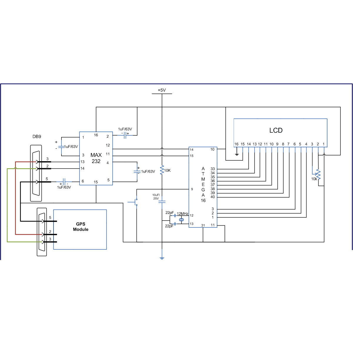
This article shows how to interface the GPS modem with ATmega16 and extract the location (latitude and longitude) from the GPGGA string and display it on LCD.

The connection of GPS modem with AVR microcontroller (ATmega 16) is shown in the circuit diagram. The ground pin of max 232 and serial o/p of GPS modem is made common. Pin2 of MAX232 is connected to pin 3 of GPS modem and pin 3 of max 232 is connected to pin 2 of modem. This type of connection is called a serial cross cable.
    Pin 2 of MAX232         -->             Pin 3 of GPS Modem
    Pin 3 of MAX232         -->             Pin 2 of GPS Modem
    Pin 5 Ground Pin of MAX232 -->   Pin 5 Ground of GPS Modem

The commonly available GPS modem gives output in serial (RS232) form. The output consists of a series of string.

String format:
The following is an example of the output string from the GPS module with its explanation. This output strings contains information about latitude, longitude, time etc and will always start with $GPGGA. Refer NMEA Standards for more details on string formats.

An example string has been given and explained below:
 $GPGGA,100156.000,2650.9416,N,07547.8441,E,1,08,1.0,442.8,M,-42.5,M,,0000*71
1.      A string always start from ‘$’ sign
2.      GPGGA :Global Positioning System Fix Data
3.      ‘,’ Comma indicates the separation between two values
4.      100156.000 : GMT time as 10(hr):01(min):56(sec):000(ms)
5.      2650.9416,N: Latitude 26(degree) 50(minutes) 9416(sec) NORTH
6.      07547.8441,E: Longitude 075(degree) 47(minutes) 8441(sec) EAST
7.      1 : Fix Quantity 0= invalid data, 1= valid data, 2=DGPS fix
8.      08 :  Number of satellites currently viewed.
9.      1.0: HDOP
10.  442.8,M : Altitude (Height above sea level in meter)
11. -42.5,M :         Geoids height
12.    __ , DGPS data
13. 0000 : DGPS data
14. *71 : checksum

The following algorithm is used to extract the latitude and longitude information from the GPS module using $GPGGA string and display it on a LCD:
1.      Get data in UDR and check weather that data is equal to $. If the data matches go to step(2) else get a new data.
2.      Get data byte by byte and check if the received byte is equal to GPGGA
3.      If the step (2) matches completely then  go to step (4) else go back to step(1)
4.      Leave first comma and wait till second comma (since we not looking for time).
5.      Start taking data in an array lati_value[ ] till the next comma.
6.      Get latitude direction in lati_dir
7.      Do the same for longitude
8.      Display the values on LCD and go back to step (1).


// Program to get latitude and longitude value from GPS modem and display it on LCD:
/*
LCD DATA port----PORT A
signal port------PORT B
    rs-------PB0
    rw-------PB1
    en-------PB2
*/

#define F_CPU 12000000UL

#include
#include

#define USART_BAUDRATE 4800
#define BAUD_PRESCALE (((F_CPU / (USART_BAUDRATE * 16UL))) - 1)


#define LCD_DATA PORTA        //LCD data port

#define ctrl PORTB
#define en PB2        //enable signal
#define rw PB1        //read/write signal
#define rs PB0        //resister select signal

void LCD_cmd(unsigned char cmd);
void init_LCD(void);
void LCD_write(unsigned char data);
void LCD_write_string(unsigned char *str);

void usart_init();
unsigned int usart_getch();

unsigned char value,i,lati_value[15],lati_dir, longi_value[15], longi_dir, alti[5] ;

int main(void)
{
    DDRA=0xff;        //LCD_DATA port as out put port
    DDRB=0x07;        //ctrl as out put
    init_LCD();        //initialization of LCD
    _delay_ms(50);        // delay of 50 mili seconds
    LCD_write_string("we at");
    LCD_cmd(0xC0);       
    usart_init();        // initialization of USART
    while(1)
    {
        value=usart_getch();
        if(value=='$')
        {
            value=usart_getch();
            if(value=='G')
            {
                value=usart_getch();
                if(value=='P')
                {
                    value=usart_getch();
                    if(value=='G')
                    {
                        value=usart_getch();
                        if(value=='G')
                        {
                            value=usart_getch();
                            if(value=='A')
                            {
                                value=usart_getch();
                                if(value==',')
                                {
                                    value=usart_getch();
                                    while(value!=',')
                                    {
                                        value=usart_getch();
                                    }
                                    lati_value[0]=usart_getch();
                                    value=lati_value[0];
                                    for(i=1;value!=',';i++)
                                    {
                                        lati_value[i]=usart_getch();
                                        value=lati_value[i];
                                    }
                                    lati_dir=usart_getch();
                                    value=usart_getch();
                                    while(value!=',')
                                    {
                                        value=usart_getch();
                                    }
                                    longi_value[0]=usart_getch();
                                    value=longi_value[0];
                                    for(i=1;value!=',';i++)
                                    {
                                        longi_value[i]=usart_getch();
                                        value=longi_value[i];
                                    }
                                    longi_dir=usart_getch();
                                    LCD_cmd(0x01);
                                    _delay_ms(1);
                                    LCD_cmd(0x80);
                                    _delay_ms(1000);
                                    i=0;
                                    while(lati_value[i]!='\0')
                                    {
                                        LCD_write(lati_value[j]);
                                        j++;
                                    }
                                    LCD_write(lati_dir);
                                    LCD_cmd(0xC0);
                                    _delay_ms(1000);
                                    i=0;
                                    while(longi_value[i]!='\0')
                                    {
                                        LCD_write(longi_value[i]);
                                        i++;
                                    }
                                    LCD_write(longi_dir);
                                    _delay_ms(1000);
                                                           
                                }
                            }
                        }
                    }
                }
            }
        }
    }
}

void init_LCD(void)
{
    LCD_cmd(0x38);        //initialization of 16X2 LCD in 8bit mode
    _delay_ms(1);

    LCD_cmd(0x01);        //clear LCD
    _delay_ms(1);

    LCD_cmd(0x0E);        //cursor ON
    _delay_ms(1);

    LCD_cmd(0x80);        // ---8 go to first line and --0 is for 0th position
    _delay_ms(1);
    return;
}


void LCD_cmd(unsigned char cmd)
{
    LCD_DATA=cmd;
    ctrl =(0<
    _delay_us(40);
    ctrl =(0<
    //_delay_ms(50);
    return;
}


void LCD_write(unsigned char data)
{
    LCD_DATA= data;
    ctrl = (1<
    _delay_us(40);
    ctrl = (1<
    //_delay_ms(50);                       
    return ;
}


void usart_init()
{
  
    UCSRB |= (1<
    UCSRC |= (1 << URSEL) | (1 << UCSZ0) | (1 << UCSZ1); // Use 8-bit character sizes

    UBRRL = BAUD_PRESCALE; // Load lower 8-bits of the baud rate value into the low byte of the UBRR register
    UBRRH = (BAUD_PRESCALE >> 8); // Load upper 8-bits of the baud rate value into the high byte of the UBRR register
}


unsigned int usart_getch()
{

    while ((UCSRA & (1 << RXC)) == 0); // Do nothing until data have been recieved and is ready to be read from UDR
    return(UDR); // return the byte
}

void LCD_write_string(unsigned char *str)    //take address vaue of the string in pionter *str
{
    int i=0;
    while(str[i]!='\0')                // loop will go on till the NULL charaters is soon in string
    {
    LCD_write(str[i]);                // sending data on CD byte by byte
    i++;
    }
    return;
}

How to interface RFID with AVR microcontroller (ATmega16)

       Knowingly or unknowingly the RFID technology is used by us in our day to day life. The most familiar example is seen in MNCs, schools and offices for daily attendance or automatic door opening system. The RFID contains two parts, namely, tag and receiver modem. When an RFID tag comes in the range of receiver, the tag gets activated and transmits its unique identification code to the receiver module.
       The output of the RFID receiver is the unique ID in either serial (RS232) or wiegand format. Most of the receivers are equipped with additional hardware to send the extracted code in the above format, which can then be used by digital signal processors. This article shows the interfacing of ATmega16 with RFID.


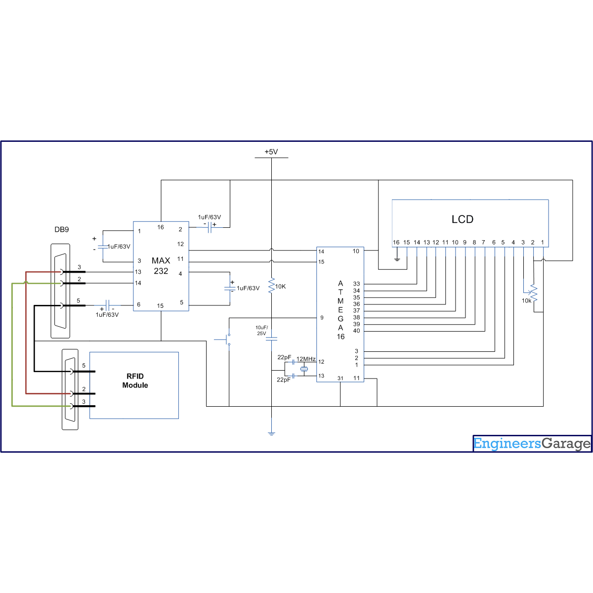
The RFID module used here gives a 12 byte unique ID of a particular tag in serial RS232 logic level format. Hence a level converter MAX232 is used in between RFID receiver module and microcontroller. The connections of RFID module and ATmega16 are shown in thecircuit diagram. The ground pin of MAX232 and serial output of RFID module is made common.  A cross cable connection is set up between the RFID module and the MAX232 by connecting transmitter pin of one to the receiver pin of the other and vice versa as shown in the circuit diagram.

Note: In case the output of the RFID module is in TTL format, there is no need of MAX232. In such a case the output of the RFID module can be directly given to the microcontroller.
 Pin 2 of max 232    Pin 3 of RFID modem
Pin 3 of max 232    Pin 2 of RFID modem
Pin 5 ground pin of max 232    Pin 5 ground of RFID modem


Code description
In order to understand the code for RFID (given below) which is interfaced with ATmega16, one must have a basic knowledge of serial communication and LCD. The serial data from RFID module can be taken by microcontroller either by polling or by using serial interrupt concepts. (To understand the difference between them, refer to tutorial on Interrupts) This article explores the interfacing of RFID module with AVR microcontroller (ATmega16) using the polling technique. The code described here keeps monitoring the serial input till it receives all the twelve bytes from the RFID module.

Receiving 12 byte serial interrupt data by polling method:
Steps to receive twelve byte serial data
        i.            Initialize USART in read mode.
       ii.            Get a 12 byte string (RFID card no.)
void getcard_id(void)    // Function to get 12 byte ID no. from rfid card
{  
    for(i=0;i<12;i++)
    {
        card[i]= usart_getch();    // receive card value byte by byte
    }
    return;
}
      iii.            Display that 12 byte data on LCD.
void LCD_display(void)    // Function for displaying ID no. on LCD
{
    for(i=0;i<12;i++)
    {
        LCD_write(card[i]);    // display card value byte by byte
    }
    return;
}


// Program to get the 12 byte string and display it on LCD by Polling method:
/*
The RFID unique code is been displayed on LCE
LCD DATA port----PORT B
ctrl port------PORT D
    rs-------PD0
    rw-------PD1
    en-------PD2
*/

#define F_CPU 12000000UL

#define USART_BAUDRATE 9600
#define BAUD_PRESCALE (((F_CPU / (USART_BAUDRATE * 16UL))) - 1)

#include
#include

#define LCD_DATA PORTA        // LCD data port
#define ctrl PORTB
#define en PB2        // enable signal
#define rw PB1        // read/write signal
#define rs PB0        // register select signal

void LCD_cmd(unsigned char cmd);
void init_LCD(void);
void LCD_write(unsigned char data);

void usart_init();
unsigned int usart_getch();

unsigned char i, card[12];
void getcard_id(void);
void LCD_display(void);

int main(void)
{
    DDRA=0xff;        //LCD_DATA port as output port
    DDRB=0x07;        //ctrl as out put
    init_LCD();        //initialization of LCD
    delay_ms(50);        // delay of 50 milliseconds
    usart_init();        // initiailztion of USART
    LCD_write_string("Unique ID No.");    //Function to display string on LCD
    while(1)
    {
        getcard_id();    // Function to get RFID card no. from serial port
        LCD_cmd(0xC0);    // to go in second line and zeroth position on LCD
        LCD_display();        // a function to write RFID card no. on LCD
    }
    return 0;
}

void getcard_id(void)    //Function to get 12 byte ID no. from rfid card
{   
    for(i=0;i<12;i++)
    {
        card[i]= usart_getch();    // receive card value byte by byte
    }
    return;
}

void LCD_display(void)    //Function for displaying ID no. on LCD
{
    for(i=0;i<12;i++)
    {
        LCD_write(card[i]);    // display card value byte by byte
    }
    return;
}

void init_LCD(void)
{
    LCD_cmd(0x38);        //initializtion of 16x2 LCD in 8bit mode
    _delay_ms(1);

    LCD_cmd(0x01);        //clear LCD
    _delay_ms(1);

    LCD_cmd(0x0E);        //cursor ON
    _delay_ms(1);

    LCD_cmd(0x80);        // ---8 go to first line and --0 is for 0th position
    _delay_ms(1);
    return;
}

void LCD_cmd(unsigned char cmd)
{
    LCD_DATA=cmd;
    ctrl =(0<
    _delay_ms(1);
    ctrl =(0<
    _delay_ms(50);
    return;
}

void LCD_write(unsigned char data)
{
    LCD_DATA= data;
    ctrl = (1<
    _delay_ms(1);
    ctrl = (1<
    _delay_ms(50);           
    return ;
}

void usart_init()
{
    UCSRB |= (1 << RXEN) | (1 << TXEN);   // Turn on the transmission and reception circuitry
    UCSRC |= (1 << URSEL) | (1<
                                                            // Use 8-bit character sizes

    UBRRL = BAUD_PRESCALE;     // Load lower 8-bits of the baud rate value..
                            // into the low byte of the UBRR register
    UBRRH = (BAUD_PRESCALE >> 8); // Load upper 8-bits of the baud rate value..
                                  // into the high byte of the UBRR register
}

unsigned int usart_getch()
{
    while ((UCSRA & (1 << RXC)) == 0); // Do nothing until data have been received..
                       // and is ready to be read from UDR
    return(UDR); // return the byte
}

void LCD_write_string(unsigned char *str)    // take address value of the string in pointer *str
{
    int i=0;
    while(str[i]!='\0')        // loop will go on till the NULL characters is soon in string
     {
        LCD_write(str[i]);    // sending data on LCD byte by byte
        i++;
    }
    return;
}

How to interface Servo Motor with AVR Microcontroller (ATmega16)

      Servo motors find huge applications in industries in the field of automation, control & robotics. The servo motors are well known for their precise control and work on the principle of servo mechanism. The servo motors can be made to run at precise angle using PWM. The PWM (pulse width modulation) is the basic working principle behind a servo motor (For more details about PWM refer Phase correct PWM mode). This article explores the interfacing of servo motor with ATmega16. Also to know more about servo mechanism see Interfacing Servo Motor with 8051.
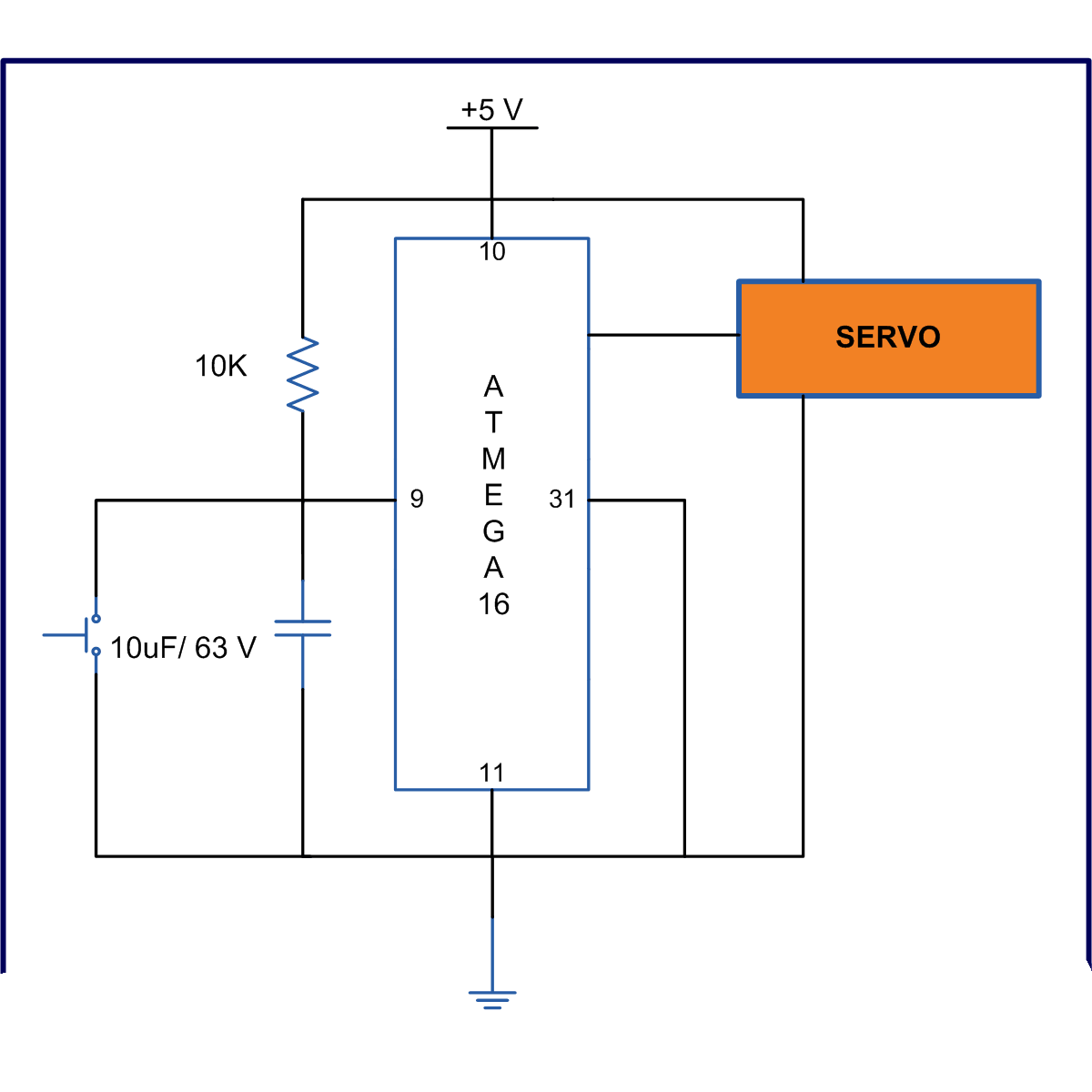
       There are different types of servos available in the market. This article bounds its scope to interfacing a commonly available servo, widely used by hobbyist with ATmega16. Such a servo consists of three wires positive supply, ground and a control signal. Unlike other motors, Servo motors don’t require any driver. When a PWM signal is applied to its control pin the, the shaft rotates to a specific angle depending on the duty cycle of the pulse.

In the above figure the ON time for pulse is 1ms and off time pulse is 18ms this rotates the shaft to -90 degree. Similarly if the on time of pulse is 1.5ms and the off time of pulse same the servo rotates to 00 and if ON time pulse increases to 2ms it rotates to +900. This gives a complete 180 degree rotation. The motor maintains its position for every corresponding signal.

Note: Before starting with servo first check the lowest ON pulse which rotates servo to -90 degree and the highest ON pulse which rotates the servo to +90 degree while keeping the OFF pulse constant. While experimenting with VS2 servo motors it was found that for -90degree the ON pulse required was 50us and OFF pulse was 18ms. And for +90 degree the ON pulse was 2050us and keep the OFF time same as 18ms. Things may differ on the type and quality.


A continuous pulse of 50 us ON time and 18ms OFF time rotates the axis of servo to -90 degree.
while(1)
{
    Motor =(1<<servo);
    _delay_us(50);
    Motor = (0<<servo);
    _delay_ms(18);

If the ON time is increased the rotation angle also increases.
The given code rotates the servo axis by 20 degree after every 5 sec.

// Program to rotate servo at the step of 20 degree.
#include<avr/io.h>
#include<util/delay.h>

#define motor PORTD
#define servo PD6

void degree(unsigned int );

int main(void)
{
    unsigned int degree_value,time;
    DDRD=0b01000000;
    for(degree_value=0;degree_value<180;degree_value +=20)
    for(time=0;time<50;time++)
    {
        degree(degree_value);
    }
    return 0;
}

void degree(unsigned int k)
{
    k=50+(k*10);
    motor= (1<< servo);
    _delay_us(k);
    motor = (0<<servo);
    _delay_ms(18);
}

How to interface serial ADC0831 with AVR microcontroller (ATmega16)

       ADC is an electronics device that converts the analog signals to digital number proportional to the magnitude of voltage. The ADC chips like ADC0804, ADC0809 etc., give 8-bit digital output. The controller device needs eight pins to receive the 8-bit data (For more details about ADC refer to Using Inbuilt ADC of AVR). Some applications need higher resolution ADCs, (10 or higher bits digital data output) for data accuracy.
       Using parallel ADCs is one option for such applications. However using parallel ADC will increase the size of the hardware as a 10-bit parallel ADC will have 10 output lines. Also you might have to use controller with higher number of pins. The other option is to use serial ADC, which needs smaller number of pins. Since the data is transmitted serially, the data transfer rate of the serial ADC is low as compared to parallel ADC. They can serve as a very good alternative in applications where speed of data transfer in not a critical point. This article explores interfacing of serial ADC0831 with ATmega16.

Circuit description:
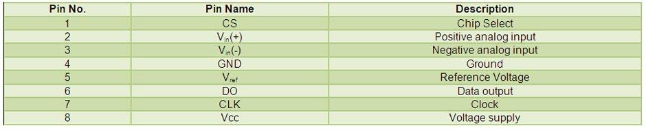
The connection of ADC0831 with ATmega16 is shown in the circuit diagram. The output of variable resistor is connected to Vin(+) and Vin(-) pin is grounded. The Pins CS, CLK and DO of ADC are connected to microcontroller.

Programming steps:
1. Send a high to low pulse to CS pin to initialize conversion.
2. Monitor the status of D0 bit until it goes low.
3. Send a clock pulse.
4. Receive the data bits from DO pin of ADC 0831.
5. Store the data bits in a variable by using bitwise operation.
6. When the data byte is received from serial ADC, display it on LCD.


// Program to interface serial ADC 0831 with AVR microcontroller (ATMEGA 16)
#include<avr/io.h>
#include<util/delay.h>
#include<inttypes.h>

#define DO PD2
#define CLK PD1
#define CS PD0

#define lcdport PORTA
#define rs PB0
#define rw PB1
#define en PB2

void lcd_init(void);
void lcdcmd(unsigned char);
void lcddata(unsigned char);
void adc_conversion(unsigned char);
void twi_init();
unsigned char adc_read();

int main()
{
    unsigned char data[12]= "ADC OUTPUT:";

    int i=0;
    unsigned char bits=0;

    DDRA=0xFF;
    DDRB=0x07;
    DDRD=~_BV(DO);    //DO pin is input pin and rest of the pins are output pins
    DDRC=0xFF;
    PORTD=0x07;


    lcd_init();
    while(data[i]!='\0')
    {
        lcddata(data[i]);
        _delay_ms(5);
        i++;
    }
               
    while(1)
    {   
        PORTD|=(1<<CS);            // high-to-low pulse is provided to CS pin
        _delay_ms(1);
        PORTD&=~(1<<CS);
        _delay_ms(1);
                           
        while(PIND & _BV(DO)) // wait until 0 bit is received
        {
            PORTD|=(1<<CLK);
            _delay_ms(1);
            PORTD&=~(1<<CLK);
            _delay_ms(1);
        }
       
        PORTD|=(1<<CLK);        // a clock pusle is provided
        _delay_ms(1);
        PORTD&=~(1<<CLK);
        _delay_ms(1);   
                   
        for(i=0;i<8;i++)       
        {
            PORTD|=(1<<CLK);    // data receive when pulse is high
            _delay_ms(1);
            bits=bits<<1;        //"bits" is variable to store data.left shift operation is perform to make place for upcoming bit

            if(bit_is_set(PIND,DO))    // if 1 is received
            bits |=1;            // bits is increment by 1
           
            PORTD&=~(1<<CLK);        // pulse low
            _delay_ms(1);
        }
       
    adc_conversion(bits);        //
    }
           
   
}

/* this function is written to convert interger value to their corresponding ASCII value*/

void adc_conversion(unsigned char adc_out) 
{
    unsigned int adc_out1;
    int i=0;
    char position=0xC2;

    for(i=0;i<=2;i++)
    {
    adc_out1=adc_out%10;
    adc_out=adc_out/10;
    lcdcmd(position);
    lcddata(48+adc_out1);
    position--;
    }
}

void lcd_init()            // fuction for LCD initialization
{
    lcdcmd(0x38);
    lcdcmd(0x0C);
    lcdcmd(0x01);
    lcdcmd(0x06);
    lcdcmd(0x80);
}

void lcdcmd(unsigned char cmdout)   
{
    lcdport=cmdout;
    PORTB=(0<<rs)|(0<<rw)|(1<<en);
    _delay_ms(10);
    PORTB=(0<<rs)|(0<<rw)|(0<<en);
}


void lcddata(unsigned char dataout)
{
    lcdport=dataout;
    PORTB=(1<<rs)|(0<<rw)|(1<<en);
    _delay_ms(10);
    PORTB=(1<<rs)|(0<<rw)|(0<<en);
}

How to interface AVR microcontroller with PC using USART (RS232 protocol)

       This article covers data transmission using 8 bit USART. The readers should have a basic understanding of serial communication and how to receive the serial data output. More  details on these topics  are available on Serial communication using AVR Microcontroller USART.
       The registers of USART system are already explained in previous article. Before transmitting the data, it must be stored in UDR register. The HyperTerminal software is used to show received data. The following steps can be followed to transmit the data to COM port of computer.
        i.            Monitor the status of UDRE (USART Data register Empty) flag.
       ii.            A high on the UDRE indicates that the UDR register is empty and ready to accept new data to be sent.
void usart_putch(unsigned char send)
{
    while ((UCSRA & (1 << UDRE)) == 0); // Do nothing until UDR is ready..
                                        // for more data to be written to it
    UDR = send; // Send the byte
}

// Program to receive data from USART and displaying that..
// data on LCD and sending the same data on HyperTerminal.
/*
get data from serial port and displaying it on LCD and send back to the HyperTerminal
LCD DATA port----PORT A
ctrl port------PORT B
    rs-------PB0
    rw-------PB1
    en-------PB2
@ external clock frequency 12MHz
*/

#define F_CPU 12000000UL

#define USART_BAUDRATE 9600
#define BAUD_PRESCALE (((F_CPU / (USART_BAUDRATE * 16UL))) - 1)

#include<avr/io.h>
#include<util/delay.h>

#define LCD_DATA PORTA        // LCD data port
#define ctrl PORTB
#define en PB2        // enable signal
#define rw PB1        // read/write signal
#define rs PB0        // register select signal

void LCD_cmd(unsigned char cmd);
void init_LCD(void);
void LCD_write(unsigned char data);
void LCD_clear();

void usart_init();
void usart_putch(unsigned char send);
unsigned int usart_getch();

int main()
{
    unsigned char value;
    DDRA=0xff;       
    DDRB=0x07;       
    init_LCD();        //initialization of LCD
    _delay_ms(50);        // delay of 50 mili seconds
    usart_init();        // initialization of USART
    while(1)
    {
        value=usart_getch();    // get data from serial port
        LCD_cmd(0xC0);           
        LCD_write(value);        // write data to LCD
        usart_putch(value);        // send data back to the PC (HyperTerminal)
    }
    return 0;
}

void init_LCD(void)
{
    LCD_cmd(0x38);        //initialization of 16X2 LCD in 8bit mode
    _delay_ms(1);

    LCD_cmd(0x01);        // clear LCD
    _delay_ms(1);

    LCD_cmd(0x0E);        // cursor ON
    _delay_ms(1);

    LCD_cmd(0x80);        // ---8 go to first line and --0 is for 0th position
    _delay_ms(1);
    return;
}

void LCD_cmd(unsigned char cmd)
{
    LCD_DATA=cmd;
    ctrl =(0<<rs)|(0<<rw)|(1<<en);   
    _delay_ms(1);
    ctrl =(0<<rs)|(0<<rw)|(0<<en);   
    _delay_ms(50);
    return;
}

void LCD_write(unsigned char data)
{
    LCD_DATA= data;
    ctrl = (1<<rs)|(0<<rw)|(1<<en);   
    _delay_ms(1);
    ctrl = (1<<rs)|(0<<rw)|(0<<en);   
    _delay_ms(50);   
    return ;
}

void usart_init()
{
    UCSRB |= (1 << RXEN) | (1 << TXEN);  
                    // Turn on the transmission and reception circuitry
    UCSRC |= (1 << URSEL) | (1<<USBS) | (1 << UCSZ0) | (1 << UCSZ1);
                    // Use 8-bit character sizes

    UBRRL = BAUD_PRESCALE; // Load lower 8-bits of the baud rate value..
                            // into the low byte of the UBRR register
    UBRRH = (BAUD_PRESCALE >> 8); // Load upper 8-bits of the baud rate value..
                                    // into the high byte of the UBRR register
}

void usart_putch(unsigned char send)
{
    while ((UCSRA & (1 << UDRE)) == 0); // Do nothing until UDR is ready..
                            // for more data to be written to it
    UDR = send; // Send the byte
}

unsigned int usart_getch()
{
    while ((UCSRA & (1 << RXC)) == 0);
                // Do nothing until data have been received and is ready to be read from UDR
    return(UDR); // return the byte
}
  
DOWNLOADS
Get Hyperterminal And Virtual Serial Port Emulator(VSPE) From Downloads.


How to interface keypad with AVR microcontroller (ATmega16)

       Keypad is most widely used input device to provide input from the outside world to the microcontroller. The keypad makes an application more users interactive.  The concept of interfacing a keypad with the ATmega16 is similar to interfacing it with any other microcontroller. The article of Interfacing keypad with 8051 can be referred for detailed description of the methodology used here. This article explains the interfacing of a 4x3 keypad with AVR microcontroller (ATmega16) and displaying the output on a LCD.

The algorithm and detailed explanation for keypad interfacing is given in above mentioned article. The brief steps to interface the keypad with AVR are written below:
1.                  Configure the row pins or column pins.
2.                  Make all output pins to low and input pins to high.
3.                  Keep monitoring the port value, where the key pad is connected.
while(1)
    {
        PORTD=0xF0;        //set all the input to one
        value=PIND;        //get the PORTD value in variable “value”
        if(value!=0xf0)        //if any key is pressed value changed
        {
            check1();
            check2();
            check3();
            check4();
        }
    }
4.                  If there is any change in port value, make one of the output pin of port to zero and rest all high.
void check1(void)
{
    //DDRD = 0xf0;
    pad =0b11111110;
    //pad &= (0<<r1);
    _delay_us(10);
    if(bit_is_clear(PIND,c1))
    LCD_write('1');
    else if(bit_is_clear(PIND,c2))
    LCD_write('2');
    else if(bit_is_clear(PIND,c3))
    LCD_write('3');
}
5.                  If any of input pin found zero, write the particular pin data to LCD, else continue with the step (4).


// Program to get input from keypad and display it on LCD.
#include<avr/io.h>
#include<util/delay.h>

#define pad PORTD
#define r1 PD0
#define r2 PD1
#define r3 PD2
#define r4 PD3

#define c1 PD4
#define c2 PD5
#define c3 PD6

void check1(void);
void check2(void); 
void check3(void);
void check4(void);

#define LCD_DATA PORTA        //LCD data port

#define ctrl PORTB
#define en PB2        //enable signal
#define rw PB1        //read/write signal
#define rs PB0        //resister select signal

void LCD_cmd(unsigned char cmd);
void init_LCD(void);
void LCD_write(unsigned char data);

unsigned int press;

int main()
{
    unsigned char value;
    DDRA=0xff;        //LCD_DATA port as output port
    DDRB=0x07;        //signal as out put
    DDRD=0x0F;
    pad=0xf0;
    init_LCD();        //initialization of LCD
    LCD_write_string("press a key");
    LCD_cmd(0xc0);


    while(1)
    {
        PORTD=0xF0;        //set all the input to one
        value=PIND;        //get the PORTD value in variable “value”
        if(value!=0xf0)        //if any key is pressed value changed
        {
            check1();
            check2();
            check3();
            check4();
        }
    }
    return 0;
}

void check1(void)
{
    //DDRD = 0xf0;
    pad =0b11111110;
    //pad &= (0<<r1);
    _delay_us(10);
    if(bit_is_clear(PIND,c1))
    LCD_write('1');
    else if(bit_is_clear(PIND,c2))
    LCD_write('2');
    else if(bit_is_clear(PIND,c3))
    LCD_write('3');
}


void check2(void)
{
    pad=0b11111101;
    /pad &= (0<<r2);
    _delay_us(10);
    if(bit_is_clear(PIND,c1))
    LCD_write('4');
    else if(bit_is_clear(PIND,c2))
    LCD_write('5');
    else if(bit_is_clear(PIND,c3))
    LCD_write('6');
}

void check3(void)
{
    pad=0b11111011;
    //pad &= (0<<r3);
    _delay_us(10);
    if(bit_is_clear(PIND,c1))
    LCD_write('7');
    else if(bit_is_clear(PIND,c2))
    LCD_write('8');
    else if(bit_is_clear(PIND,c3))
    LCD_write('9');
}

void check4(void)
{
    pad =0b11110111;
    //pad &= (0<<r4);
    _delay_us(10);
    if(bit_is_clear(PIND,c1))
    LCD_write('#');
    else if(bit_is_clear(PIND,c2))
    LCD_write('0');
    else if(bit_is_clear(PIND,c3))
    LCD_write('*');
}


void init_LCD(void)
{

    LCD_cmd(0x38);        //initializtion of 16X2 LCD in 8bit mode
    _delay_ms(1);

    LCD_cmd(0x01);        //clear LCD
    _delay_ms(1);

    LCD_cmd(0x0E);        //cursor ON
    _delay_ms(1);

    LCD_cmd(0x80);        // ---8 go to first line and --0 is for 0th position
    _delay_ms(1);
    return;
}


void LCD_cmd(unsigned char cmd)
{
    LCD_DATA=cmd;
    ctrl =(0<<rs)|(0<<rw)|(1<<en);    // making RS and RW as LOW and EN as HIGH
    _delay_ms(1);
    ctrl =(0<<rs)|(0<<rw)|(0<<en);    // making RS, RW , LOW and EN as LOW
    _delay_ms(50);
    return;
}


void LCD_write(unsigned char data)
{
    LCD_DATA= data;
    ctrl = (1<<rs)|(0<<rw)|(1<<en);    // making RW as LOW and RS, EN as HIGH
    _delay_ms(1);
    ctrl = (1<<rs)|(0<<rw)|(0<<en);    // making EN and RW as LOW and RS HIGH
    _delay_ms(50);                        // give a 10 milli second delay to get thigs executed
    return ;
}

void LCD_write_string(unsigned char *str)    //take address vaue of the string in pionter *str
{
    int i=0;
    while(str[i]!='\0')                // loop will go on till the NULL charaters is soon in string
    {
        LCD_write(str[i]);                // sending data on CD byte by byte
        i++;
    }
    return;
}